Facebook Storage Infrastructure: How Facebook Cuts Costs by Managing BLOB Storage Life Cycle


A couple of weeks ago, I published an article about how facebook serves millions of photos per second which discussed the design of the Haystack Storage System.
Facebook’s corpus of photos, videos, and other Binary Large Objects (BLOBs) that need to be reliably stored and quickly accessible is massive and continues to grow and as the footprint of BLOBs increases, storing them in the traditional storage system, Haystack, is becoming increasingly inefficient.
This article explains a paper which discusses the design of a new storage system called f4 that facebook designed and deployed to use for warm storage (as opposed to Haystack which will exclusively be used for hot storage). It's very important to note that f4 is not a replacement to Haystack, it's just a new storage sub-system in the overall BLOB storage system.
If you didn't read the Haystack article, be sure to check it out here, but nonetheless, you can still read this article just knowing that there is an older storage system called Haystack that's used for hot storage (new content) and that we want to move warm (old content) to a new, more space efficient storage system.
Introduction
As you may have learned from the article about Haystack is that it's designed to have a very large throughput in order to be able to serve both traffic on newly uploaded content and traffic on the long-tail (older) content. It also achieves reliability via triple replication to 3 geographically distinct locations.
The interesting observation here is that content on facebook, whether it's photos, videos, files, chat attachments, etc. gets less popular as it grows older and thus gets requested much less than when it was just uploaded. This hints us that if we store this older content in Haystack, we will be wasting a massive amount of IOPS (IOs per second) available to those storage machines due to the fact that they will be receiving much less traffic. But on the other hand, we will need more machines to store older content because it continues to grow (as the paper mentions, as of February 2014, Facebook stored over 400 billion photos).
So the main ideas we will discuss in this article are:
- Understand the correlation between content age and traffic patterns.
- Determine a time threshold after which content will be moved from the hot storage (Haystack) into the warm storage (f4) which allows facebook to store warm content differently to be more space efficient.
- Determine how a new storage sub-system for warm storage will fit within the existing storage infrastructure.
- Design the warm storage system (f4) to satisfy the following design goals:
- The new system has to be more space efficient (due to the large and increasing size of the content).
- The new system has to have an acceptable latency (it's allowed to have higher latency and less maximum throughput than hot storage).
- The new system has to solve the problem of over-provisioning that results from Haystack's triple replication, yet achieve the same reliability and fault tolerance guarantees as Haystack.
- Evaluate the savings the new system will introduce as opposed to the old system.
The Case for Warm Storage
This section of the paper motivates the creation of a warm storage system at Facebook. It demonstrates that temperature zones exist, content age is a good proxy for temperature and that warm content is large and growing.
Methodology
The data presented in this section is derived from a two-week trace which includes a random \(0.1\%\) of reads, \(10\%\) of creates and \(10\%\) of deletes.
Data is presented for nine user-facing BLOB types, namely, Profile Photos, Photos, HD Photos, Mobile Sync Photos, HD Mobile Sync Photos, Group Attachments, Videos, HD Videos and Message (chat) Attachments. Some of those BLOB types such as, attachments can exist in many different formats (text, pdfs, etc.).
Temperature Zones Exist
To make the case for warm storage the paper first shows that temperature zones exist, i.e., that content begins as hot, receiving many requests and then cools over time, receiving fewer and fewer requests.
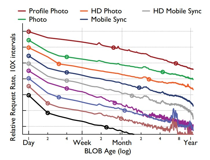
The previous graph was generated from the two-week \(0.1\%\) reads trace. It shows the relative request rate per object per hour bucketed by day on the x-axis and the points mark order of magnitude decreases.
As we can see from the graph, the existence of temperature zones is clear in the trend of decreasing request rates over time. For all nine types, content less than one day old receives more than 100 times the request rate of one-year-old content.
Differentiating Temperature Zones
Given that temperature zones exist, the next questions to answer are how to differentiate warm from hot content and when it is safe to move content to warm storage. Note that BLOBs are only read or deleted and never modified, so we only need to examine the read and delete rates.
To determine this, the following graph was constructed from the trace data collected:
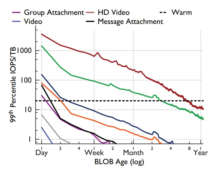
The graph shows the \(99^{th}\) percentile request load for the BLOB types under observation. The reason for choosing the \(99^{th}\) percentile here is that it gets us as close as possible to the worst case request load so that system will be resilient enough to maintain an acceptable latency even at a near-worst-case scenario.
The data in the graph is bucketed by the time interval it takes to create \(1TB\) of that BLOB type (so for instance, if 1 TB of a type is created every 3600 seconds, then the first bucket is for ages of 0-3599 seconds, the second is for 3600-7200 seconds and so on) and the y-axis is denormalized to be on per IOPS/TB basis.
f4 is meant to have \(4TB\) disks that can deliver a maximum of 80 Input/Output Operations Per Second (IOPS) while keeping per-request latency acceptably low. So now we need to find when each BLOB type goes under 20 IOPS/TB so that its IOPS needs can be satisfied by f4.
From the dotted horizontal line in the graph, we can see that 7 of the 9 BLOB types go under 20 IOPS/TB in less than a month (for some types, it's even less than a week).
A similar analysis was done for the deletes rate (the paper mentions that it was not as rigorous) and the result of combining both analysis yields an age of a month as a safe threshold between hot and warm content for all but two BLOB types. One type, Profile Photos, is never moved to warm storage. The other, Photos, uses a three months threshold.
Warm Content is Large and Growing
The part to prove in this case is that the percentage of content that is warm is large and continuing to grow thus merits the needs for a specialized system.
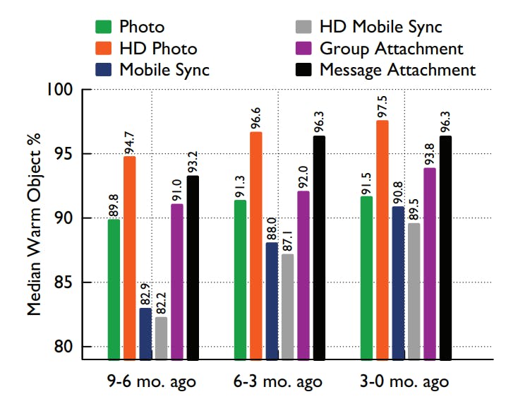
The previous graph shows the median percentage of warm objects of each BLOB type bucketed by 3-month intervals of age. And as we can see, warm content is a large percentage of all objects: in the oldest interval more than \(80\%\) of objects are warm for all types. It also shows that the warm fraction is increasing: in the most recent interval more than \(89\%\) of objects are warm for all types.
This proves that warm content is large and will continue to get large over time and thus the need for a new system to efficiently handle warm storage alongside Haystack.
BLOB Storage Design
In this section we will discuss the overall design of BLOB storage system at facebook after adding the new warm storage system f4 (In a later section, I will discuss the design of f4 itself).
As we may have noticed from the Haystack article, facebook design seems to be shooting for building as simple components as possible because they will be easier to reason about and easier to maintain in production.
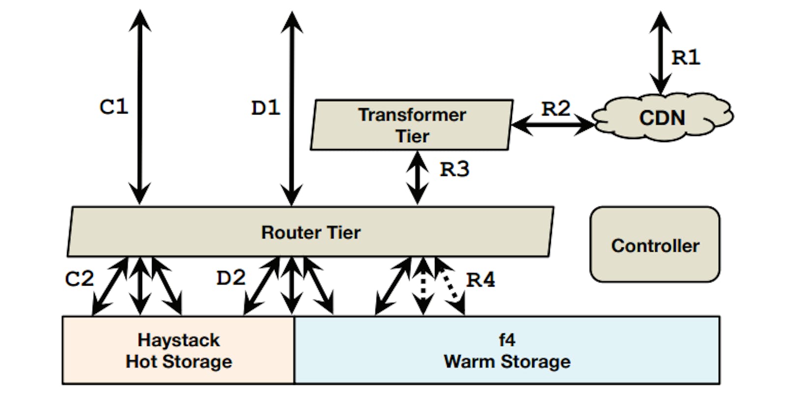
The following diagram shows the overall BLOB storage system at facebook (at that time):
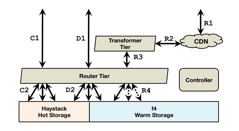
Creates (C1-C2), deletes (D1-D2), and reads (R1-R4). Creates are handled by Haystack, most deletes are handled by Haystack, reads are handled by either Haystack or f4.
The flow for each operation type is as follows:
- Creates: enter the system at the router tier (C1) and are directed to the appropriate host in the hot storage system (C2).
- Deletes: enter the system at the router tier (D1) and are directed to the appropriate hosts in appropriate storage system (hot or warm) (D2).
- Reads: enter the system at the caching stack (R1) and, if there is a cache miss, traverse through the transformer tier (R2) to the router tier (R3) that directs them to the appropriate host in the appropriate storage system (R4).
The storage system defines the concept of a volume by grouping BLOBs together in logical volumes that are backed by physical volumes (actual disks). Volumes can either be locked (read and delete only) or unlocked (append, read and delete). Volumes transition from the unlocked state to the locked state when they are full (100GB at that time).
Now let's take a look at what each of those components does:
- Controller: The controller ensures the smooth functioning of the overall system. It helps with provisioning new store machines, maintaining a pool of unlocked volumes, ensuring that all logical volumes have enough physical volumes backing them, creating new physical volumes if necessary, and performing periodic maintenance tasks such as compaction and garbage collection.
- Router Tier: The router tier is the interface of BLOB storage as it hides the implementation of storage and enables the addition of new subsystems like f4. The router machines maintain a soft-state copy of the logical-to-physical volume mappings. They route operations as follows:
- Reads: the router extracts the logical volume id from the BLOB id and finds the physical mapping of that volume. It chooses one of available physical volumes— typically, the volume on the closest machine—and sends the request to it. In case of failure, a timeout fires and the request is directed to the next physical volume.
- Creates: the router picks a logical volume with available space, and sends the BLOB out to all physical volumes for that logical volume. In case of any errors, any partially written data is ignored to be garbage collected later, and a new logical volume is picked for the create.
- Deletes: the router issues deletes to all physical replicas of a BLOB. Responses are handled asynchronously and the delete is continually retried until the BLOB is fully deleted in case of failure.
- Transformer Tier: The transformer tier handles a set of transformations on the retrieved BLOB. For example, these transformations include resizing and cropping photos. In the old system, those transformations were performed on the storage machines which was not optimal. This new configuration enables the independent scaling of the transformer machines and the ability to choose different machine types that are more compute-optimized (note that storage machines are more disk optimized).
- Caching Stack: Reads are initially directed to a caching stack to absorb traffic on popular content and protect the storage system from excessive traffic spikes.
- Hot Storage with Haystack: This is the hot storage system we discussed in this article. This will handle all creates, most deletes (because most deletes are for newer content) and some reads (only reads for the objects resident inside it).
- Warm Storage with f4: This is the new system we will discuss in the remainder of this article.
f4 Design
Now let's take a look at the design of the warm storage system f4. But before we discuss the design, let's first re-iterate our design goals:
- Storage efficiency: One of the key goals of the new system is to improve storage efficiency, i.e., reduce the effective-replication-factor while still maintaining a high degree of reliability and performance. Note that the old replication factor that Haystack needed was \(3.6\): 3 replicas of the same BLOB and each replica is stored in RAID-6 format, so \(3*1.2=3.6\). f4 will need to somehow have a lower replication rate in order to be more storage efficient.
- Fault-tolerance: Another important goal for our storage system is fault tolerance to a hierarchy of faults to ensure we do not lose data and that storage is always available for client requests. The paper considers 4 different types of failures:
- Drive failures, at a low single digit annual rate.
- Host failures, periodically.
- Rack failures, multiple time per year.
- Data center failures, extremely rare and usually transient, but potentially more disastrous.
f4 Overview
f4 is comprised of a number of cells where each cell lives entirely within a data center and is comprised of homogeneous hardware (cells use 14 racks of 15 hosts with 30 4TB drives per host). A cell is treated as a unit of acquisition and as a unit of deployment and roll out which means that you can't add half a cell to your storage capacity and also you can't shutdown or roll a release out to half a cell.
A cell is responsible for reliably storing a set of locked volumes (note that because f4 is used only for warm storage, it only handles reads and deletes, so no need to have any unlocked volumes) and uses Reed-Solomon coding to store these volumes with lower storage overhead.
Without going down the rabbit hole of the mathematics involved in Reed-Solomon, simply put, Reed-Solomon is one of the most commonly used Distributed Erasure Coding methods. Erasure coding is used to achieve the same reliability constraints of normal replication while using lower storage but at a higher latency. A Reed-Solomon\((n, k)\) code encodes \(n\) bits of data with \(k\) extra bits of parity and can tolerate \(k\) failures, at an overall storage size of \(n + k\).
In f4, instead of bits, we deal with data blocks (each of size 1GB) and so we get the following partitions:
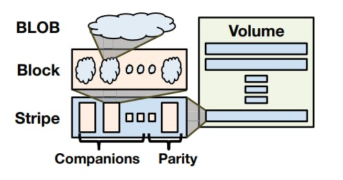
As we can see from the previous diagram, a BLOB is split into blocks, each group of blocks are called companions, each group of companions along with their Solomon-Reed parity blocks are called a stripe and a group of stripes comprise a volume.
We will talk more about why this format is used and what other methods are used in a dedicated section for fault tolerance in f4.
The f4 Cell
Individual f4 cells are resilient to disk, host, and rack failures and are the primary location and interface for the BLOBs they store. Each f4 cell handles only locked volumes, i.e., it only needs to support read and delete operations against that volume. The data and index files are read-only. The haystack journal files that track deletes are not present in f4. Instead, all BLOBs are encrypted with keys that are stored in an external database. Deleting the encryption key for a BLOB in f4 logically deletes it by making it unreadable.
The index files are very small so they use a normal triple replication approach to avoid the hassle of encoding them since the storage savings won't be that worth it anyway.
The data file on the other hand, contains the actual BLOBs and thus large in size, so it's encoded using Solomon-Reed\(10,4\). The file is logically divided up into contiguous sequences of \(n\) blocks, each of size \(1GB\). For each such sequence of \(n\) blocks, \(k\) parity blocks are generated, thus forming a logical stripe of size \(n + k\) blocks.
The block size is chosen to be a large value such as, \(1GB\) because it first decreases the number of BLOBs that span multiple blocks and thus require multiple I/O operations to read. Second, it reduces the amount of per-block metadata that f4 needs to maintain.
An f4 cell looks like so:
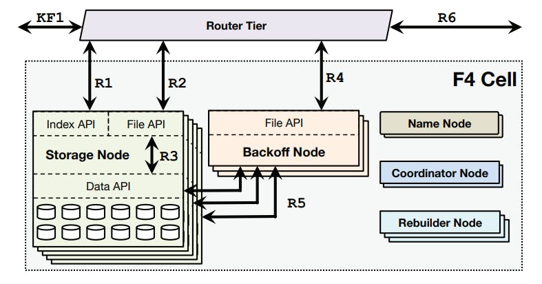
Now let's take a look at what each of those components does.
Name Node
The name node maintains the mapping between data blocks and parity blocks and the storage nodes that hold the actual blocks. Name nodes are made fault tolerant with a standard primary backup setup.
Storage Nodes
The storage nodes are the main component of a cell and handle all normal-case reads and deletes. Storage nodes expose two APIs:
- Index API: which provides existence and location information for volumes.
- File API: which provides access to data.
Reads (R1) are handled by validating that the BLOB exists and then redirecting the caller to the storage node with the data block that contains the specified BLOB:
- Normal-case reads: are redirected to the appropriate storage node (R2) that then reads the BLOB directly from its enclosing data block (R3).
- Failure-case reads: use the Data API to read companion and parity blocks needed to reconstruct the BLOB on a backoff node. Note that the reconstruction is not one in the storage node because it's computationally expensive.
The router tier fetches the per-BLOB encryption key and the BLOB is then decrypted on the router tier. Note that decryption is computationally expensive and performing it on the router tier allows f4 to focus on efficient storage and allows decryption to be scaled independently from storage.
Backoff Nodes
As we saw in the failure-case reads, when there are failures in a cell, some data blocks will become unavailable and serving reads for the BLOBs it holds will require online reconstruction of them from companion data blocks and parity blocks which is computationally expensive. So Backoff nodes are storage-less, CPU-heavy nodes that handle the online reconstruction of the requested BLOBs.
Each backoff node exposes a File API that receives reads from the router tier after a normal-case read fails (R4). The backoff node sends read requests to the equivalent offsets from all \(n − 1\) companion blocks and \(k\) parity blocks for the unavailable block (R5). Once it receives \(n\) responses it decodes them to reconstruct the requested BLOB.
Note that Backoff nodes only handle the reconstruction of the requested BLOB, it does not rebuild the full block because the size of a BLOB is typically much smaller than the block. The full reconstruction of blocks is handled in the background by the Rebuilder nodes.
Rebuilder Nodes
As mentioned above, Rebuilder nodes are responsible for reconstructing corrupt blocks in the background. Rebuilder nodes are also storage-less, CPU-heavy nodes.
Rebuilding is a heavyweight process that imposes significant I/O and network load on the storage nodes so Rebuilder nodes throttle themselves to avoid adversely impacting online user requests.
Scheduling the rebuilds to minimize the likelihood of data loss is the responsibility of the coordinator nodes.
Coordinator Nodes
A cell requires many maintenance tasks, such as scheduling block rebuilding and ensuring that the current data layout minimizes the chances of data unavailability. Coordinator nodes are storage-less, CPU-heavy nodes that handle these cell-wide tasks.
Another very important task that coordinator nodes perform is re-balancing the data blocks layout to achieve the needed fault tolerance guarantees. This means that data blocks has to be laid out in a special configuration to work and when failures and rebuilds happen, some violations of the layout might occur and the coordinator's job to spot those violations and schedule re-balancing tasks to restore the needed layout (more on this in the section about fault tolerance).
Evaluation of Design Goals
Now let's look back at how the previously mentioned design achieved the stated design goals.
Fault Tolerance
As mentioned before, we need f4 to be able to survive disks, hosts, racks and data center failures. This is handled via 2 methods:
1. Distributed Erasure Coding
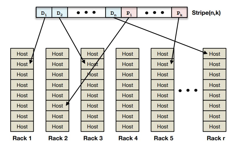
This is used to handle failures related to disks, hosts and racks. As we mentioned before, f4 uses Reed-Solomon\((10,4)\) per cell which is able to survive the loss of 4 datablocks. Given that data blocks are laid out correctly across different racks (note that if blocks have different racks, it means that they are on different hosts and this different disks), it will provide the needed fault tolerance to those types of failures.
The following diagram shows a sample layout of blocks in a stripe across racks.
2. XOR Geo-Replication
The remaining fault that we didn't address so far is the failure of an entire data center. This handled in f4 by an XOR geo-replication. This means that:
- An entire copy of the same data exists in a second data center.
- The XOR result of the 2 copies in the 2 data centers is stored in a third data center.
But how does that guarantee across-datacenter fault tolerance? The answer is simple by reviewing the properties of XOR:
- \(a \oplus b = c\)
- \(a \oplus c = b\)
- \(b \oplus c = a\)
This means that if we lose either of \(a\) or \(b\) or \(c\), we can reconstruct the lost copy by simply XOR-ing the 2 remaining copies.
You might be left wondering, why don't we just regenerate the lost copy from the other copies without having to use an XOR replication. The answer to this is that XOR replication is more storage efficient (will be discussed in the next section).
Storage Efficiency
As mentioned before, Haystack had a replication factor of \(3.6\): 3 replicas of the same BLOB and each replica is stored in RAID-6 format, so \(3*1.2=3.6\).
f4 on the other hand doesn't use conventional replication, instead it uses Distributed Erasure Coding as we mentioned before. The used encoding, Reed-Solomon\((10,4)\) stores every 10 blocks as 14 blocks (including parity blocks), so it has a replication factor of \(14/10=1.4\) per cell.
Also cells are XOR geo-replicated, so we have 2 copies, each with a replication factor of \(1.4\) and an XOR copy with a replication factor of \(1.4\) so we get a total replication factor of \(\frac{2*1.4 + 1.4}{2} = 2.1\). This why XOR-replication is used.
To calculate the storage savings in f4, let:
- \(repl_{hay} = 3.6\) be the effective replication factor for Haystack.
- \(repl_{f4} = 2.1\) be the effective replication factor of f4.
- \(del_{f4} = .068\) be the fraction of BLOBs in f4 that are deleted.
- \(logical_{f4} ~ 65PB\) be the logical size of BLOBs stored in f4.
Then the reduction in storage space from f4 is:
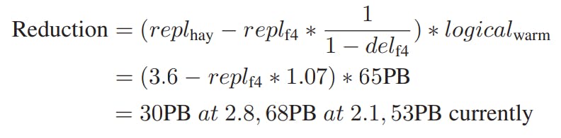
Note that the XOR geo-replication at the time the paper was written was still being rolled out. That's why it's calculated for both replication factors \(2.8\) and \(2.1\).
Conclusion
Facebook’s BLOB corpus is massive, growing, and increasingly warm. The paper made a case for a specialized warm BLOB storage system, described an overall BLOB storage system that enables warm storage, and gave the design of f4. f4 reduces the effective-replication-factor of warm BLOBs from 3.6 to 2.1; is fault tolerant to disk, host, rack, and datacenter failures; provides low latency for client requests; and is able to cope with the lower throughput demands of warm BLOBs.
Future Discussions
After a while of operating f4 in production, facebook decided that operating 2 different storage systems (Haystack and f4) was such an operational hassle and it also introduced some waste in terms of resources. In a later paper, facebook introduces the Tectonic Storage System which consolidates both hot and warm storage into a single system that's more efficient and easier to operate. I will probably publish an article discussing its design in the few coming weeks.